Build multi-account AWS connectivity with VPC Lattice as the sole network fabric
Rahul Sahotay, Amazon Web Services
Summary
As a multi-account AWS
There is another way to draw the line. Instead of every account owning its connectivity, you build it once in a central Network account and let workload accounts consume it. This pattern uses Amazon VPC Lattice
It is worth being precise about where this fits. VPC Lattice routes by DNS name and service network, not by IP address, so this is a cost-effective alternative for the service-access, egress, and ingress patterns, not a wholesale replacement for IP routing. Transit Gateway
What this pattern gives you
Connectivity cost that tracks the number of environments (three), not the number of accounts (hundreds)
Zero-touch onboarding: one VPC association delivers full AWS-service access and filtered egress
Centralized, FQDN-filtered internet egress governed by a single allowlist
Environment isolation enforced by IAM auth policies
and OU-scoped resource sharing Overlapping workload CIDRs supported by design, because routing never depends on IP addresses
One fabric that serves internal workloads and external, on-premises, and cross-Region consumers alike, through Service Network Endpoints
The shared fabric is deployed once in the Network account and exposed through three environment-scoped service networks
Prerequisites and limitations
Prerequisites
An active AWS account
An AWS account set aside as the central Network account
, where the shared fabric will live. AWS Organizations
enabled in all-features mode, with workload accounts sorted into organizational units (OUs) for dev, test, and prod. All-features mode is required for OU-scoped resource sharing and the aws:PrincipalOrgPathspolicy conditions, the OU structure is what later scopes who can reach which environment.AWS Resource Access Manager (RAM)
sharing with AWS Organizations turned on in the management account ( aws ram enable-sharing-with-aws-organization). Without it, the OU-scoped service network shares cannot target OUs.A Region where Amazon VPC Lattice, including Resource Gateways and Resource Configurations, is available.
Comfort with core AWS networking (VPCs, subnets, DNS, security groups) and multi-account building blocks (AWS Organizations, OUs, RAM).
For the reference implementation: AWS CDK (TypeScript) or AWS CloudFormation tooling configured.
A landing zone such as AWS Control Tower
or Landing Zone Accelerator on AWS is not required. If you have one, the reference implementation integrates with it by re-pointing its SSM parameter paths to your framework's existing network ID parameters.
Limitations
VPC Lattice routes by DNS name and service network, not by IP. It is not suited for general-purpose, IP-routed east-west traffic between workload VPCs, hybrid routing (AWS Direct Connect or VPN), or centralized traffic inspection with firewall appliances. Retain Transit Gateway for those.
A VPC Lattice custom domain name is fixed once the resource is created. Changing it means deleting and recreating the resource, which drops its associations and Resource Configurations, so choose names deliberately.
Service networks are Regional. A multi-Region footprint repeats the pattern once per Region.
A single DNS record cannot serve both the Service Network Endpoint path and the VPC-association path at once. When both coexist, you need split-horizon DNS (covered in Best practices).
Resource Gateway subnets should be /24 or larger. The gateway scales its network interfaces with connection volume, and undersized subnets risk IP exhaustion that shows up as intermittent, hard-to-diagnose connectivity failures.
The shared egress proxy is a concentration point. Deploy it across multiple Availability Zones and monitor it (again, see Best practices).
The fabric carries a fixed base cost, so the economics work best once you are past roughly 15 to 30 accounts. Below that, per-account networking may still be cheaper.
Some AWS services aren't available in all AWS Regions. For Region availability, see AWS services by Region
. For specific endpoints, see the Service endpoints and quotas page, and choose the link for the service.
Product versions
Amazon VPC Lattice with Resource Gateways, Resource Configurations, and Service Network Endpoints (generally available as of re:Invent 2024).
AWS CDK v2 (the reference implementation targets
aws-cdk-lib2.150.0 or later on Node.js 20).AWS CLI v2 for the CloudFormation path.
Squid proxy on Amazon ECS on AWS Fargate.
Architecture
Target technology stack
Three VPC Lattice service networks (dev, test, prod) in a central Network account
Resource Gateways and Resource Configurations exposing 10 shared interface VPC endpoints (the CloudFormation path adds an 11th,
execute-api)A Squid forward proxy on Amazon ECS on AWS Fargate (2 tasks) behind an internal Network Load Balancer, exposed as a Resource Configuration for filtered egress
Service Network Endpoints for external, on-premises, and cross-Region ingress
AWS RAM shares scoped to OUs; IAM auth policies scoped by OU path
Target architecture
Everything in this pattern is built once in the central Network account and offered outward, so a workload account gains its connectivity the moment it creates a single VPC association. Three pillars sit on that one shared fabric:
Pillar | What it provides | How it works |
|---|---|---|
Shared AWS service endpoints | Centralized access to SSM, STS, ECR, ECS, CloudWatch Logs, and more | 10 endpoints in an Endpoint VPC, exposed as VPC Lattice Resource Configurations |
Centralized egress | Filtered outbound internet access with an FQDN allowlist | Squid forward proxy on ECS Fargate (2 tasks) behind an internal NLB, exposed via Resource Configuration |
Ingress via Service Network Endpoints | External, on-premises, and cross-Region consumers reaching shared services | Service Network Endpoints (SN-E) allow consumers outside the VPC Lattice association to connect |

Figure 1: High-level topology showing the three pillars on a single VPC Lattice fabric.

Figure 2: Shared endpoint data flow. A workload VPC resolves an AWS service domain through the VPC Lattice-managed Private Hosted Zone, and traffic reaches the shared interface endpoint in the Network account through the Resource Gateway.

Figure 3: Centralized egress data flow. A workload sends outbound traffic to the shared Squid proxy through the service network, where an FQDN allowlist filters the request before it leaves through the Network account.
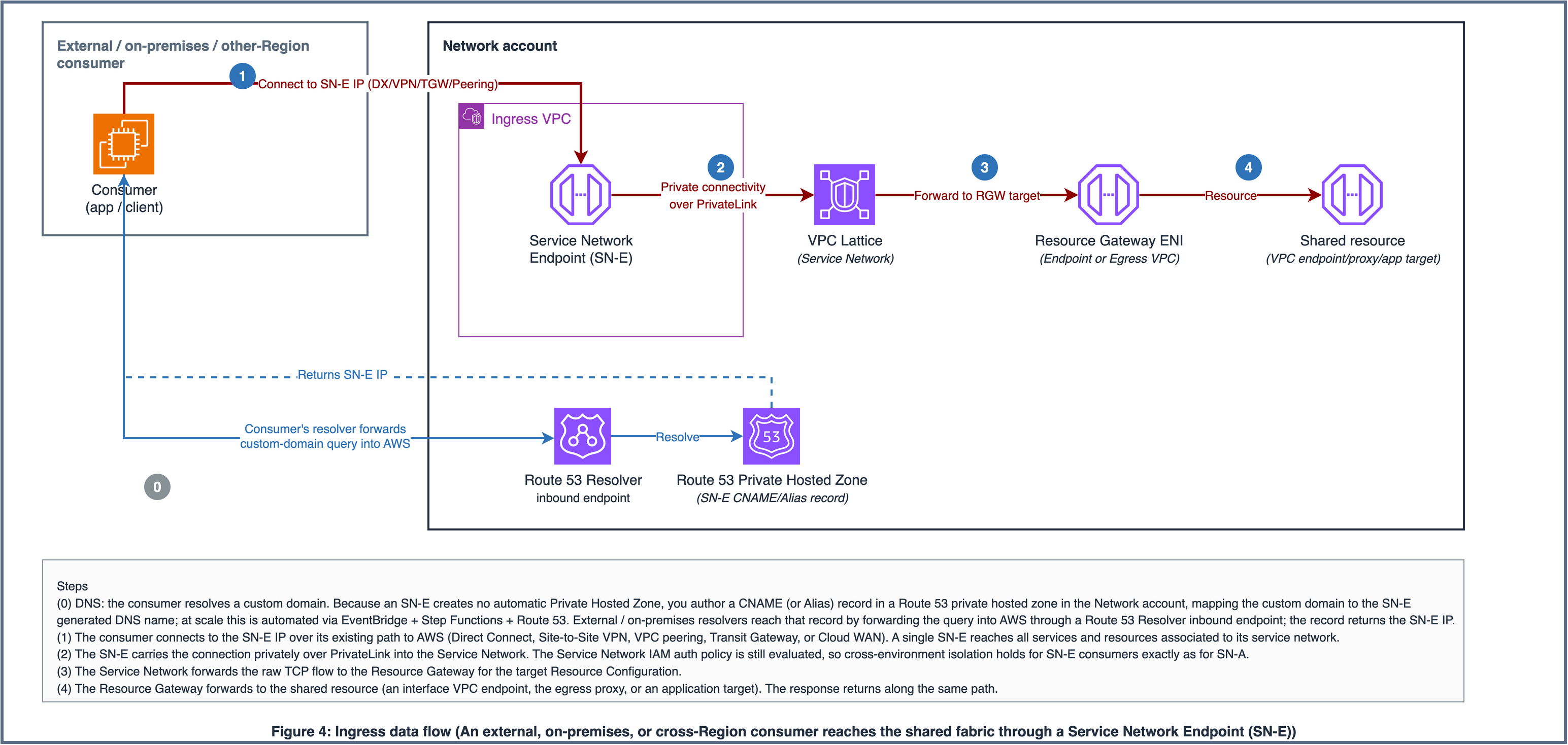
Figure 4: Ingress data flow. External, on-premises, and cross-Region consumers reach shared services through a Service Network Endpoint in the ingress VPC.
Automation and scale
Onboarding a workload account is deliberately dull: one VPC association with PrivateDnsEnabled, plus a security group that permits egress to the VPC Lattice managed prefix list, rolled out at scale through a service-managed AWS CloudFormation StackSet or AWS CDK. VPC Lattice creates Private Hosted Zones automatically so standard AWS service domains (for example, ssm.us-east-2.amazonaws.com) resolve to Lattice addresses129.224.0.0/17 range with no per-workload DNS configuration.
Tools
AWS services
VPC Lattice
provides the service networks, Resource Gateways, Resource Configurations, and Service Network Endpoints that form the connectivity fabric. Resource Access Manager
(RAM) shares the service networks with workload OUs. AWS Organizations
provides the OU structure that scopes RAM shares and IAM auth policies. CloudFormation StackSets
roll the workload VPC association out to every current and future account in a target OU. Systems Manager Parameter Store
carries the contract between stacks: VPC, subnet, and security group IDs are published once and resolved at deploy time, with no hardcoded IDs. ECS on Fargate
runs the Squid egress proxy. Elastic Load Balancing
(Network Load Balancer) fronts the egress proxy. CodeBuild
and Elastic Container Registry (Amazon ECR) build and store the custom Squid image with its FQDN allowlist. Route 53
provides the Private Hosted Zones used for DNS resolution, plus the Resolver inbound endpoint that lets on-premises consumers resolve ingress domains. EventBridge
, Step Functions , and DynamoDB power the Lambda-free ingress DNS automation, which keeps custom-domain records current as Resource Configurations change. Systems Manager
, Security Token Service , ECR , ECS , and CloudWatch Logs are among the shared endpoint services exposed through the fabric.
Code
The reference implementation is in the GitHub repository aws-samples/sample-vpc-lattice-multi-account-connectivity, provided in both AWS CDK (TypeScript, 14 stacks) and AWS CloudFormation (11 templates), with 4 architecture diagrams and 15 documentation files.
Best practices
These recommendations apply to the shared-fabric model described in this pattern. They cost nothing to adopt on day one and become expensive to retrofit later. Apply them before onboarding your first wave of workload accounts.
Naming: make names a contract, not decoration
VPC Lattice resource names are functional. The workload association automation looks up the target Service Network
Prescriptive recommendation: Pick one short, lowercase, org-wide prefix and build every name from the same ordered parts: prefix, scope or service, environment, role. Note that only Service Networks and Service Network Endpoints are per-environment; Resource Gateways
Per environment:
  sn-dev-shared              (dev Service Network)
  sn-test-shared             (test Service Network)
  sn-prod-shared             (prod Service Network)
  sne-dev-ingress            (Service Network Endpoint for dev ingress)

Shared across environments:
  net-endpoint-resource-gw   (Resource Gateway, one per Endpoint VPC)
  net-egress-resource-gw     (Resource Gateway, one per Egress VPC)
  ssm-endpoint-rc            (Resource Configuration, one per exposed service)
  squid-proxy-rc             (Resource Configuration for the egress proxy)
Encode the environment, never the account: environment is the unit of isolation in this pattern, so it belongs in the name; account identity belongs in tags.
Why this matters: Consistent naming enables automated lookup, simplifies IAM policy conditions, and makes CloudTrail
Tagging: make every resource attributable from day one
Tags drive cost allocation
Mandatory tag set:
Tag key | Purpose | Example value |
|---|---|---|
| Maps to Service Network (dev/test/prod) |
|
| Identifies IaC ownership |
|
| Drives chargeback |
|
| Cross-references the parent Service Network |
|
Assign explicit security groups to every resource that creates an ENI
If your landing zone (AWS Landing Zone Accelerator
Finalize naming and custom domains before you create resources
VPC Lattice custom domain names cannot be changed after a resource is created. Changing a domain requires deleting and recreating the resource, which drops all of its associations and Resource Configurations. Lock the naming convention above before the first deploy.
Use split-horizon DNS when ingress (SN-E) and VPC-association paths coexist
A single DNS record cannot serve both paths. The Service Network Endpoint path resolves to the endpoint's per-AZ secondary IPs, while the VPC-association path resolves to VPC Lattice-managed IPs in the 129.224.0.0/17 range. If an Ingress VPC with Service Network Endpoints coexists with workload VPCs that associate directly, use separate Private Hosted Zones
Enable RAM organization sharing before standing up the fabric
OU-scoped Resource Access Manageraws ram enable-sharing-with-aws-organization). Do this first, or the shares fail.
Monitoring: the trade-off for centralization
The shared-fabric model concentrates connectivity into fewer components. This is both its strength (one place to govern, secure, and observe) and its primary operational trade-off (a failure in the shared fabric affects all consumers). Centralized monitoring is not optional; it is the trade you make for reducing per-account overhead.
Day-one observability:
VPC Lattice access logs
to CloudWatch Logs or S3, enabled on each Service Network for both the SERVICE and RESOURCE log types (they are off by default) Resource Gateway health via CloudWatch
metrics (target health, connection count) NLB target group health for the egress proxy (unhealthy targets = egress outage)
ECS task health for the Squid proxy (running count, restart rate)
CloudWatch alarms on: Resource Configuration unhealthy targets, NLB 5xx rate, proxy task restart count, and spikes in Squid denied requests (either a misconfigured workload or a genuine exfiltration attempt; both are worth knowing about)
Quota planning
Track usage against the quotas that matter for this pattern. Defaults are Region-specific and adjustable through AWS Support
Quota | Default | Notes |
|---|---|---|
Service networks per Region | 50 | 3 used (dev, test, prod). Ample headroom. |
VPC associations per service network | 500 | The real scaling ceiling. Alarm at 80% (400) and request an increase proactively. |
Resource configurations per service network | 500 | About 11 used (10 endpoints plus egress). Comfortable. |
Resource gateways per VPC | 500 | 1 to 2 used per VPC. Comfortable. |
Service network VPC endpoints per service network | 200 | Relevant to the ingress (SN-E) pattern. |
The practical takeaway: at a hundreds-of-accounts estate, the binding limit is VPC associations per service network (500). Environment-scoped service networks keep you well inside it; if a single environment approaches 400 associations, request an increase early.
Auth policy design: scope to OU paths, not account IDs
Service Network IAM auth policiesaws:PrincipalOrgPaths conditions rather than listing individual account IDs. New accounts added to an OU automatically inherit access without policy updates. The reference implementation pairs the OU-path match with an organization ID check as a second boundary:
{
  "Effect": "Allow",
  "Principal": "*",
  "Action": "vpc-lattice-svcs:Invoke",
  "Resource": "*",
  "Condition": {
    "StringEquals": {
      "aws:PrincipalOrgID": "o-EXAMPLE12345"
    },
    "ForAnyValue:StringLike": {
      "aws:PrincipalOrgPaths": [
        "o-EXAMPLE12345/r-EXAMPLE/ou-EXAMPLE-dev0000/*"
      ]
    }
  }
}
Why this matters: Account-ID-based policies require updates every time you onboard a new account, which defeats the zero-touch onboarding promise. OU-path conditions make the policy scale with the organization structure.
AWS Well-Architected Framework alignment
This pattern maps to all six pillars of the AWS Well-Architected Framework
Pillar | How this pattern aligns | Trade-off to acknowledge |
|---|---|---|
Operational Excellence | Everything is Infrastructure as Code; onboarding is a single VPC association; shared connectivity is configured once, reducing per-account drift | Platform team becomes single point of operational responsibility |
Security | Defense in depth: Service Network IAM auth policies (OU-path scoped) + OU-scoped RAM shares + centralized FQDN allowlist egress filtering + least-privilege IAM* | Centralized control requires strong platform-team access governance |
Reliability | Multi-AZ Resource Gateways; Squid proxy at desired count 2 with ECS auto-recovery and NLB health checks; no single-AZ dependency | Shared egress proxy is a concentration risk (mitigated by multi-AZ + monitoring) |
Performance Efficiency | VPC Lattice routes traffic within the AWS network without additional hops; shared endpoints eliminate per-account endpoint provisioning delays | Egress proxy adds latency vs direct NAT Gateway path (acceptable for filtered egress) |
Cost Optimization | Connectivity scales with environments (3), not accounts (hundreds); shared infrastructure reduces idle per-account resources | Fabric has a fixed base cost even at small scale (break-even typically between 20 and 30 accounts depending on endpoint count and AZ configuration) |
Sustainability | Fewer always-on resources; shared infrastructure maximizes utilization per deployed component | Minimal incremental sustainability impact |
*Follow the principle of least privilege and grant the minimum permissions required to perform a task. For more information, see Grant least privilege and Security best practices in the IAM documentation
Key trade-off: concentration risk
This pattern deliberately concentrates connectivity into a single managed fabric. This is both its strength (one place to govern, secure, and observe) and its primary risk (a failure in the shared fabric affects all consumers). Mitigations:
Multi-AZ Resource Gateways (minimum 2 subnets in different AZs, each /24 or larger so the gateway has room to scale its ENIs)
Fargate tasks at desired count >= 2 with cross-AZ placement
NLB with cross-zone load balancing enabled
CloudWatch alarms on all shared components with automated escalation
Runbook for fabric degradation (documented in the repository)
Consider a break-glass NAT Gateway path for production workloads that need egress during a fabric outage
Epics
| Task | Description | Skills required |
|---|---|---|
Deploy the three service networks |
| Network administrator |
Create the Network account VPCs and endpoints |
| Network administrator |
| Task | Description | Skills required |
|---|---|---|
Create the Resource Gateway and Resource Configurations |
| Network administrator |
| Task | Description | Skills required |
|---|---|---|
Deploy the Squid proxy and expose it via VPC Lattice |
| DevOps engineer |
| Task | Description | Skills required |
|---|---|---|
Associate the workload VPC and validate at scale |
| Network administrator |
| Task | Description | Skills required |
|---|---|---|
Deploy Service Network Endpoints and configure split-horizon DNS |
| Network administrator |
Troubleshooting
| Issue | Solution |
|---|---|
VPC association fails with "Service network not found" | The workload account has not received the RAM share. Confirm the account can see the network with |
DNS does not resolve to a Lattice IP after association | Confirm |
DNS resolves to the wrong target | A pre-existing Private Hosted Zone (often a legacy per-account endpoint PHZ) is shadowing the Lattice-managed zone. List all hosted zones associated with the workload VPC, identify the conflicting |
Resource Gateway stuck, unhealthy, or fails to deploy | Check the gateway state (expect ACTIVE), free IP addresses in each gateway subnet (exhaustion blocks ENI scaling; subnets should be /24 or larger), and the gateway security group (443 for endpoints, 3128 for egress). Landing zones that strip default security group rules cause silent timeouts here. |
403 responses from VPC Lattice | IAM auth policy denial. Retrieve the auth policy from the Service Network, walk the calling account's parent OUs to build its full org path, and compare it against the policy's |
Related resources
GitHub repository: aws-samples/sample-vpc-lattice-multi-account-connectivity
CloudFormation templates (network foundation, VPC Lattice resource gateways, Squid egress proxy, workload VPC association, workload foundation)
CDK TypeScript stacks
Architecture diagrams (.drawio + PNG + SVG)
Documentation files covering architecture, deployment phases, best practices, and troubleshooting
AWS documentation
Frameworks and tools
Related AWS Prescriptive Guidance
Pricing references
Additional information
This section quantifies what the shared-fabric model changes compared to a per-account connectivity model. The numbers are expressed in resource counts and cost drivers (per-hour, per-GB, per-endpoint-hour), not in dollars. Actual savings depend on Region, traffic volume, and the specific pricing in effect when you deploy. Validate with the AWS Pricing Calculator
Note
Organizations using Transit Gateway
What you will achieve:
Connectivity cost decoupled from account count
Onboarding time reduced from hours/days to minutes
Reduced per-account operational overhead
Platform team self-service model for workload teams
Outcome 1: Cost-predictable connectivity
The shared-fabric model changes the cost structure from per-account (scales with estate size) to per-environment (fixed at 3 regardless of estate size).
Shared endpoints consolidation:
In the per-account model, each workload VPC provisions its own interface VPC endpoints
Estate size | Per-account model: endpoint ENIs (illustrative) | Shared-fabric model | Consolidation ratio |
|---|---|---|---|
50 accounts | ~1,500 endpoint ENIs | 10 (one shared set) | ~150:1 |
150 accounts | ~4,500 endpoint ENIs | 10 | ~450:1 |
500 accounts | ~15,000 endpoint ENIs | 10 | ~1,500:1 |
Business impact. Connectivity-to-AWS-services cost stops scaling with account count. The 151st or 501st account onboards with zero incremental endpoint spend.
Centralized egress consolidation:
In the per-account model, highly available outbound access means one NAT Gateway
Estate size | Per-account model: NAT Gateways (2 per account) | Shared-fabric model: centralized egress | Consolidation ratio |
|---|---|---|---|
50 accounts | 100 NAT Gateways | 1 shared egress path | 100:1 |
150 accounts | 300 NAT Gateways | 1 shared egress path | 300:1 |
500 accounts | 1,000 NAT Gateways | 1 shared egress path | 1,000:1 |
Business impact. Egress cost consolidates into one managed path that the platform team owns and right-sizes centrally.
Transit Gateway attachment reduction (for these patterns only):
For the specific patterns covered here (AWS-service access and filtered egress), VPC Lattice routes traffic without a TGW hop:
Estate size | Per-account model: TGW attachments for these patterns | Shared-fabric model | Change |
|---|---|---|---|
50 accounts | 50 attachments | 0 (Lattice routes directly) | Attachments not needed for these patterns |
150 accounts | 150 attachments | 0 | Same |
500 accounts | 500 attachments | 0 | Same |
Important
If your accounts also carry east-west or hybrid traffic through TGW, those attachments remain. The change applies only to attachments that existed solely for centralized service-access and egress patterns. If TGW serves multiple purposes in your environment, your per-account attachment may still be needed.
Outcome 2: Reduce per-account operational overhead
The per-account model duplicates not just resources but operational work. Every endpoint, gateway, and route table must be created, secured, monitored, and kept consistent.
Onboarding contrast, per account:
Per-account model: 10 or more endpoints, 2 or more NAT gateways, route tables, Private Hosted Zones, and security groups, each created, secured, and kept in sync. Shared-fabric model: one VPC association.
DNS is manual per account in the per-account model; VPC Lattice creates the Private Hosted Zones automatically on association.
Onboarding drops from hours or days of IaC work to minutes through a single StackSet or CDK deploy, with far less configuration drift to manage.
Business impact. Platform teams shift from "deploying connectivity per account" to "maintaining one shared fabric." Workload teams get self-service: associate your VPC, start building.
Outcome 3: Centralized security governance
Consolidating connectivity into the shared fabric also consolidates its governance. Environment isolation comes from OU-scoped IAM auth policies
Outcome 4: Extend the same fabric to external and cross-Region consumers
The first three outcomes serve workloads that associate their VPC directly with a Service Network. The same fabric also reaches consumers that sit outside that association: external clients, on-premises systems (over Direct Connect or VPN), and workloads in other Regions.
A Service Network Endpoint
Business impact. One connectivity investment serves both internal workloads and external/cross-Region consumers, so you do not build and operate a parallel ingress architecture alongside the shared fabric.
How to validate the numbers for your environment
Resource-count changes are deterministic; dollar impacts depend on your traffic patterns, AZ count, Region, and account volume. Use the AWS Pricing Calculator
Is this compatible with an existing Transit Gateway deployment?
Yes. This pattern handles three specific patterns: AWS-service access, controlled internet egress, and ingress via Service Network Endpoints
Does this replace Transit Gateway?
No. This pattern is not positioned as a Transit Gateway replacement. It targets specific connectivity patterns (AWS-service access, controlled egress, and ingress) where VPC Lattice offers a simpler, more cost-predictable delivery mechanism. Transit Gateway remains the right tool for general-purpose IP routing, hybrid connectivity, and centralized traffic inspection. Many organizations will use both: TGW for east-west and hybrid traffic, VPC Lattice for service access and egress.
Our organization already uses TGW with centralized egress. What does this add?
If you already centralize egress through a TGW + NAT Gateway
No TGW attachment required in workload accounts for this traffic, which removes the per-attachment hourly charge and data-processing fee for these flows
No CIDR coordination required in workload VPCs (Lattice routes by DNS name and service network, supporting overlapping CIDRs)
Simpler onboarding: VPC association is one resource vs. TGW attachment + route table entries + subnet route updates
Evaluate whether these incremental benefits justify the migration effort for your specific environment.
What is the migration path from a per-account architecture?
Incremental and side-by-side. You never have to migrate the entire estate at once:
Stand up the fabric (Service Networks
, shared endpoints, egress proxy) in the Network account. This does not affect existing workload accounts. Pilot with one OU first (ideally a dev OU). Validate end-to-end: DNS resolves to Lattice IPs,
aws sts get-caller-identitysucceeds, egress proxy permits allowlisted domains.Onboard in waves, OU by OU, using StackSets
or CDK Pipelines. Decommission redundant per-account resources only after validation in each wave.
The association is additive and reversible. If anything looks wrong, disassociate the VPC and the account reverts to its previous connectivity.
How does this work across multiple Regions?
A VPC Lattice Service Network
Deploy three Service Networks (dev/test/prod) in each Region
Deploy shared endpoints and egress proxy in each Region's Network account VPCs
Associate workload VPCs to the Service Network in their own Region
RAM shares and auth policies are regional (create in each Region)
The IaC is parameterized by Region and instantiated once per Region.
Can I add more AWS service endpoints to the shared set?
Yes. The reference exposes 10 endpoints (SSM, STS, ECR, ECS, CloudWatch Logs, and more). To add another:
Deploy the interface VPC endpoint
in the Endpoint VPC Add the service to the endpoints array in the CDK or CloudFormation stack
Redeploy. Workloads resolve the new domain automatically through the Lattice-managed Private Hosted Zone
, with no per-account changes required.
What about overlapping CIDRs across workload accounts?
VPC Lattice supports overlapping CIDRs natively. Workload VPCs can use the same CIDR blocks because Lattice routes by DNS name and service network (DNS/HTTP), not by IP address. This is particularly valuable for large organizations where CIDR coordination across hundreds of accounts is impractical or where acquired business units bring their own address space.
What happens if the shared egress proxy goes down?
All workload accounts using the centralized egress path lose outbound internet access for traffic routed through the proxy. Mitigations:
Fargate
tasks run at desired count >= 2 across multiple AZs NLB
health checks detect and route around unhealthy tasks ECS auto-recovery replaces failed tasks automatically
CloudWatch
alarms alert the platform team immediately
For production workloads that require egress even during a fabric outage, maintain a break-glass NAT Gateway path that can be activated by changing a route table entry. This is the standard resilience pattern for any centralized egress design (TGW-based or Lattice-based).
What IP ranges does VPC Lattice resolve to?
For VPC Resources (what this pattern uses for endpoints and the egress proxy), DNS resolves to addresses in the 129.224.0.0/17 IPv4 range. This is the AWS-managed range for VPC Lattice resource traffic.
How do I update the egress allowlist without a full redeploy?
By default, the allowlist is the ALLOWED_DOMAINS environment variable on the ECS task definition, so updating it requires a stack redeploy (ECS rolls out a new task revision). For frequent changes, source the list from SSM Parameter Store
Attachments
To access additional content that is associated with this document, download and unzip the following file: attachment.zip